Python Examples#
Several example scripts are provided in the examples directory of the
repository. These examples demonstrate the core features of pyrobopath,
including:
Creating and preprocessing toolpaths
Defining robot systems
Selecting and running planners
Before running the examples, make sure you have installed
pyrobopath. Then, navigate to the examples directory:
cd examples
python3 simple_scheduling_example.py
python3 toolpath_examples.py
python3 planners_examples.py
python3 robot_number_examples.py
Toolpaths#
A toolpath is created from a collection of Contour s.
Contours represent a contiguous path that is traversed by a specified tool.
The toolpath can either be created manually, or parsed from a standard
Gcode file.
The tool representation is up to the user, but a good choice is to define each tool with an enum.
from enum import Enum

class Materials(Enum):
    MATERIAL_A = 1
    MATERIAL_B = 2
Manual Toolpath Creation#
To create a toolpath manually, we must first define a set of contours.
from pyrobopath.toolpath import Contour, Toolpath

path1 = [np.array(1.0, 0.0, 0.0), np.array(0.0, 0.0, 0.0), np.array(0.0, 1.0, 0.0)]
path2 = [np.array(1.0, 0.0, 0.0), np.array(0.0, 0.0, 0.0), np.array(0.0, 1.0, 0.0)]
path3 = [np.array(1.0, 0.0, 0.0), np.array(0.0, 0.0, 0.0), np.array(0.0, 1.0, 0.0)]

contour1 = Contour(path=path1, tool=Materials.MATERIAL_A)
contour2 = Contour(path=path2, tool=Materials.MATERIAL_A)
contour3 = Contour(path=path2, tool=Materials.MATERIAL_A)

toolpath = Toolpath()
toolpath.contours = [contour1, contour2, contour3]
Gcode Toolpath Creation#
A toolpath can be created from standard Gcode flavors.
Caution
Only the reprap flavor from slic3r has been tested thus far. It should be relatively simple to write a parser for other representations.
The gcodeparser package is used to read a Gcode file to a python representation.
from gcodeparser import GcodeParser

filepath = "<path to gcode>"
with open(filepath, "r") as f:
    gcode = f.read()
parsed_gcode = GcodeParser(gcode)
Then, the parsed Gcode is transformed to a pyrobopath Toolpath. A
contour is defined by a consecutive group of linear G1 moves that have an
extrusion value greater than 0. Contours are separated by G0 travel (rapid)
moves or G1 moves with no extrusion.
from pyrobopath.toolpath import *

toolpath = Toolpath.from_gcode(parsed_gcode.lines)
Toolpath Visualization#
After creating a toolpath with one of the methods listed above, the path can be
visualized using the pyrobopath.toolpath.visualization module. There
are functions for 2D and 3D visualization. The 2D projected visualization
separates contours by distinct Z-heights and is useful for inspecting additive
manufacturing (3D printing) paths.
from pyrobopath.toolpath.visualization import (
  visualize_toolpath,
  visualize_toolpath_projection
)

# toolpath = ...

visualize_toolpath(toolpath) # 3D
visualize_toolpath_projection(toolpath) # 2D projection
Creating a Multi-robot System#
A toolpath planner requires a system definition that defines the robot base
frame position, home position, collision model, and others. This system
definition is provided as a dictionary with the keys as agent IDs and the
values as AgentModel.
We will create a simple two robot system.
from pyrobopath.process import AgentModels
from pyrobopath.collision_detection import FCLRobotBBCollisionModel

bf1 = np.array([-350.0, 0.0, 0.0])
bf2 = np.array([350.0, 0.0, 0.0])

# create agent collision models
agent1 = AgentModel(
    base_frame_position=bf1,
    home_position=np.array([-250.0, 0.0, 0.0]),
    capabilities=[Materials.MATERIAL_A],
    velocity=50.0,
    travel_velocity=50.0,
    collision_model=FCLRobotBBCollisionModel((200.0, 50.0, 300.0), bf1),
)
agent2 = AgentModel(
    base_frame_position=bf2,
    home_position=np.array([250.0, 0.0, 0.0]),
    capabilities=[Materials.MATERIAL_B],
    velocity=50.0,
    travel_velocity=50.0,
    collision_model=FCLRobotBBCollisionModel((200.0, 50.0, 300.0), bf2),
)
agent_models = {"robot1": agent1, "robot2": agent2}
Collision Geometry#
There are a few options for defining the collision geometry of robots. Each of the provided geometries are manipulated in Cartesian space. This greatly simplifies the collision checking process, and therefore the task allocation and scheduling, for multi-robot systems.
The simplest collision geometries are the LineCollisionModel, defined
by a single line between the robot’s base and end effector, and the
LollipopCollisionModel that, in addition to the line, adds a sphere
around the end effector.
The python-fcl library is
used for more complicated collision geometries. Arguably, the most useful model
is defined by the FCLRobotBBCollisionModel. This model defines a
bounding box that is rigidly attached to the end effector of the robot and
rotates around an axis through the robot’s base. This model is shown in the
image below.
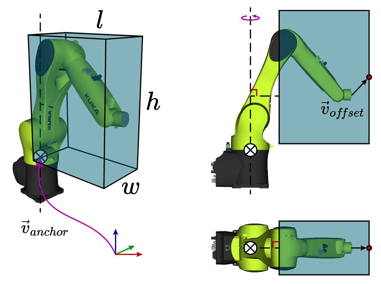
The dimensions of the bounding box are defined by the dims parameter
\(\textrm{dims}=\left(l, w, h\right)\). The anchor vector
\(\vec{v}_{anchor}\) defines the base frame location of the robot with
respect to the world, and the offset \(\vec{v}_{offset}\) defines the rigid
translation between the end effector and the center face of the bounding box.
The offset argument can be used to adjust the bounding box geometry to better
approximate the links of the robot. This can also be useful if the robot tool
geometry extends past the tool center point.